Thinking about starting with Arduino? Read!

4

Category : Arduino, Electronics

Hi

I just want to write a few words for those new to Arduinos, or those looking for tutorials, guides etc. If you haven’t got a Arduino board yet, you can get one from several places, I’ll list some of my favorite shops. And of course you also need the Arduino Software!

Sparkfun
Seeedstduio
Adafruit

Or, Modified Electronics for the great Pico! (not recommended for beginners, you’ll be better of with a normal board).

What you are looking for is the Arduino Duemilanove, the USB board. Which will suit most your needs. It’s very easy to use, and wires can be plugged right into it. Later on you might want a Boarduino or maybe a Pico as mentioned above, they are great for using in combination with breadboards! Alternatively you can get the Starter kit, almost all shops got these. Sparkfun got a nice kit, which is worth a look.

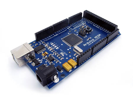
If you should want more I/Os, or just more space for code the Arduino Mega is a great choice! Or the Sanguino!

Parts!

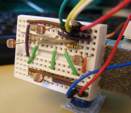
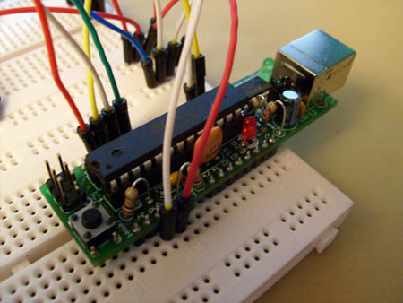
You will always need parts, resistors, leds, breadboards, wires etc. I’ll list up a few shops that I use the most.

Futurlec

Lots of cheap basic parts! recommend the resistor packs, and they also got cheap breadboards. And all of the shops mentioned above stock parts too. For jumper-wires I recommend these at seeedstudio. Futurlec also got some nice jumper-kits. For extra small breadboards these at Seeedstudio are very nice!

Pololu

Great site for robotics, motors, gearboxes etc. They also got a nice tracked chassis. They got a lot great products, sensors, motor controllers, etc.

Tutorials/Guides/etc

1. The basic guide, from sparkfun. You should start with this!

2. The Complete Beginners Guide to The Arduino

3. Adafruit’s Arduino Tutorials

4. Arduino.cc`s Tutorials

5. Arduino.cc Reference! Not tutorials, but handy!

Also the Libaries page at Arduino.cc is great! I’m sure you’ll find something to use in several projects!

Well, thats all I’ll write for now. I’m sure I left out alot, and will update this post when I find something new to add 🙂

PS. If you got any questions etc, please take it in my forums post here.

My new Serial LCD arrived!

3

Category : Arduino, Electronics

Got my Serial 16×2 LCD today, I’m still quite noob when it comes to serial. But I’m gonna put out some simple and easy to follow tutorials for stuff when I get the hang of it 🙂

Anyhow, here’s just a little youtube clip showing some of my projects today!

[youtube=http://www.youtube.com/watch?v=Sc4B0LAatDo;ap=%2526fmt%3D18&w=425&h=344]

[youtube=http://www.youtube.com/watch?v=DwIn_AbCuVw;ap=%2526fmt%3D18&w=425&h=344]

Arduino: Showing CPU load with 9 leds!

6

Category : Arduino, Electronics

My new project, is a simple led-strip which shows CPU load. 9 led’s are used for this, could have used more but my tiny breadboard couldn’t hold more. Anyhow, it uses serial communication to receive how much the totalcpu usage is. For this you need a C# program running on your computer, it just sends a value from 0-100. And the Arduino reacts and lights up leds accordingly to how much load your CPU got.

I will not go into how you make the program in C#, therefore I’m uploading the .exe here for you to download. I’ll also include the source-code for it.

What you need?

1x Arduino
9x LEDs
Some wires

1. Wire it all up like in this Fritzing picture.

2. Load up the Arduino with the following program.

3. Download the C# program here.

When you start the .exe file, you only need to select which Com port the Arduino is using. And the click connect, and then it should start communicating with the Arduino. And show cpu load.

[youtube=http://www.youtube.com/watch?v=ecbdUhiOWes&w=425&h=344]

PS. If you got any questions etc, please take it in my forums post here.

Modified Pico, a Arduino Nano, but smaller.

Category : Arduino, Electronics

Look at it?!

I just fell in love with it 😛 Also, 24$ isn’t bad. So if you’re considering the Arduino Nano, why not try this one instead?

Features:

ATmega328 running at 16MHz with external resonator (0.5% tolerance)
On-board FTDI232 USB to Serial Connection
Supports auto-reset (choose Duemilanove w/ ATmega328 in the Arduinoâ„¢ software)
Operating voltage of 2.7 – 5.5 VDC
Schottky diode reverse polarity protection
Auto-sense power input between USB and external source
Resettable 500 mA fuse for overcurrent protection
On-board pin 13 and communication LEDs

Go check it out =)

http://www.modifiedelectronics.com/mp-01.php

Bo/arduino advanced light tracker.

10

Category : Arduino, Electronics

Made a followup to my light tracker, except this one can go up and down. So it follows light in more directions than the other ones.

[youtube=http://www.youtube.com/watch?v=0Fw6ausjl9o&w=425&h=344]

Made of some cheap plastic-foam, wont last forever but long enough for me to test it.

Program Code!

PS. If you got any questions etc, please take it in my forums post here.

How to make a light tracker using arduino & photoresistors!

22

Category : Arduino, Electronics

[youtube=http://www.youtube.com/watch?v=iEhX27ahreI&w=480&h=385]

This is how to make a simple light tracker/follower with the Arduino. The components you need apart from the Arduino is:

2x Photoresistors: “PHOTOCELL2 Miniature Photocell”.
2x 470 Ohms resistors.
1x Servo.

And of course some wires, and a breadboard or two :). Next step is to wire it all up, I’ve made a drawing in Fritzing that you can follow. Basically each photoresistor is wired likes this:

PhotoR       470Ohms
+5    o—///–.–///—o GND
|
Pin 0 & 1 o——-

Program Code:

#include <Servo.h>

Servo myservo;

int pos = 0;  // Variable to store the servo position.
int inputPhotoLeft = 1; // Easier to read, instead of just 1 or 0.
int inputPhotoRight = 0;

int Left = 0; // Store readings from the photoresistors.
int Right = 0; // Store readings from the photoresistors.

void setup()
{
myservo.attach(9); // Attach servo to pin 9.
}

void loop()
{
// Reads the values from the photoresistors to the Left and Right variables.
Left = analogRead(inputPhotoLeft);
Right = analogRead(inputPhotoRight);

// Checks if right is greater than left, if so move to right.
if (Left > (Right +20))
// +20 is the deadzone, so it wont jiggle back and forth.
{
if (pos < 179)
pos++;
myservo.write(pos);
}

// Checks if left is greater than right, if so move to left.
if (Right > (Left +20))
// +20 is the deadzone, so it wont jiggle back and forth.
{
if (pos > 1)
pos -= 1;
myservo.write(pos);
}

// Added some delay, increase or decrease if you want less or more speed.
delay(10);
}

PS. If you got any questions etc, please take it in my forums post here.

Guide: How to make a 9g micro servo continuous

8

Category : Arduino, Electronics

It’s always good to have servos that works like a geared motor. That also can go in both direction and speed is adjustable, it’s very handy in robotic project or general vehicles. The servo I’m using is a Mystery Micro Servo 9g SD90. But most of these small servos got the same internals so I guess you can use this on other servos.

1. Remove the stickers on both sides, and unscrew the four long screws that goes from the bottom to the top. One in each corner of the servo.

2. Gently lift off the top cover to uncover all the gears. Notice, it’s smart to remember the correct order of the gears, so that when you put them back you know what goes where. But I took a picture close to make it easier to remember where they all go. Use picture below for this purpose.

3. Remove all gears, no need to clean the grease off. Just put them in a box just for now.

4. Take the top gear and snip the little plastic bit off it, look at pictures below. This is the part that stop the servo from going more than 180 degrees.

5. Now we need to glue the potmeter, look at picture below. Just remove the plastic cap thats on the shaft of the potmeter to show it’s internals.

6. Attach the servo to the ardunio, using pin 9 as the signal. Use this program or just some other program that gives the servo 90 degrees. If the potmeter is centered the servo should stop the motor from turning, if it doesn’t try to turn the potmeter shaft one or the other way until it stops. You now got it centered so that 90 is stop, just add some glue to the internals of the potmeter to keep it locked. Before moving onto step 7 let the glue dry.

7. You now need to cut off the end of the potmeter shaft, this keeps the potmeter shaft from moving. Look at picture below for more info.

8. Now you only need to put it all back together. Just use the picture in step 2 for reference when adding all the gears.

There you are, now it should work like a continous servo. Any questions just leave a comment below.

Video of the final product:

Arduino Mega on it’s way!

Category : Arduino, Electronics

This is a beast compared to the old Diecimila, well I’ll let the specs speak for themself. Diecimila specs in parentheses.

Arduino Mega specifications:

Microcontroller: ATmega1280 (ATmega168)
Operating Voltage: 5V
Input Voltage (recommended): 7-12V
Input Voltage (limits) : 6-20V
Digital I/O Pins: 54, of which 14 provide PWM output
(14, of which 6 provide PWM output)
Analog Input Pins: 16
DC Current per I/O Pin: 40 mA
DC Current for 3.3V Pin: 50 mA
Flash Memory: 128 KB of which 4 KB used by bootloader
(16 KB (of which 2 KB used by bootloader)
SRAM 8 KB:
(1 KB)
EEPROM 4 KB
(512 bytes)
Clock Speed 16 MHz

Yepp, pretty much outclasses the old arduino 😀

My two Arduino projects

Category : Arduino, Electronics

Well, some months ago I bough a Arduino Diecimila. To put it simple it’s a little programmable electronic board, which has some inputs and outputs. Or to be more specific:

The Arduino Diecimila is a microcontroller board based on the ATmega168. It has 14 digital input/output pins (of which 6 can be used as PWM outputs), 6 analog inputs, a 16 MHz crystal oscillator, a USB connection, a power jack, an ICSP header, and a reset button.

Anyhow, I started with some basic led stuff, like blinking leds etc. And after fooling around with that for some time, I decided to make a “landingstrip” of leds. The final outcome of that was the 8 mode selectable 10x leds strip.

Video:

Well you get the idea.

After that I made one ledstrip using almost all outputs for leds. The 12x led strip with six modes, and a potmeter to adjust speed. Also the potmeter is used to select modes when holding down the button.

Video: