How to make a security alarm using LDR and Laser!

1

Category : Arduino, Electronics

How about a easy and simple tutorial on how to make a sort of security sensor using laser and a light dependent resistor?

It’s just as simple as this, the LDR reacts when it gets less light than the laser-dot in the center of it. Which is when something comes in the lasers way. So then you know when something passes the invisible line between the laser and the LDR.

Lets begin with what components you need:

1x Laser Emitter/Pen
1x LDR
1x Resistor 10k (doesn’t have to be 10k ohms)
1x Piezo Buzzer (you can use a LED or anything else you want)

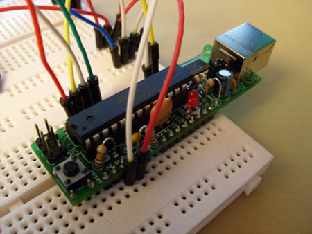
And of course a Arduino board of your choice, and some wires.

Lets wire it all up like this:

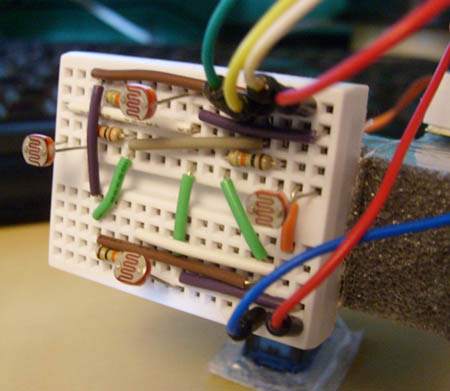
Things to notice, buzzer is grounded and the + wire is on the digital 10. Laser is just ground and +5v to make it light constantly. The LDR is in a voltage divider with a resistor, we take out the readings in the middle where the yellow wire is, and it’s attached to the analog 0.

A picture of the LDR.¨

When all this is wired up, just put this code and run it.

[youtube=http://www.youtube.com/watch?v=IzEDspdWjxU;ap=%2526fmt%3D18&w=425&h=344]

Bo/arduino advanced light tracker.

10

Category : Arduino, Electronics

Made a followup to my light tracker, except this one can go up and down. So it follows light in more directions than the other ones.

[youtube=http://www.youtube.com/watch?v=0Fw6ausjl9o&w=425&h=344]

Made of some cheap plastic-foam, wont last forever but long enough for me to test it.

Program Code!

PS. If you got any questions etc, please take it in my forums post here.

How to make a light tracker using arduino & photoresistors!

22

Category : Arduino, Electronics

[youtube=http://www.youtube.com/watch?v=iEhX27ahreI&w=480&h=385]

This is how to make a simple light tracker/follower with the Arduino. The components you need apart from the Arduino is:

2x Photoresistors: “PHOTOCELL2 Miniature Photocell”.
2x 470 Ohms resistors.
1x Servo.

And of course some wires, and a breadboard or two :). Next step is to wire it all up, I’ve made a drawing in Fritzing that you can follow. Basically each photoresistor is wired likes this:

PhotoR       470Ohms
+5    o—///–.–///—o GND
|
Pin 0 & 1 o——-

Program Code:

#include <Servo.h>

Servo myservo;

int pos = 0;  // Variable to store the servo position.
int inputPhotoLeft = 1; // Easier to read, instead of just 1 or 0.
int inputPhotoRight = 0;

int Left = 0; // Store readings from the photoresistors.
int Right = 0; // Store readings from the photoresistors.

void setup()
{
myservo.attach(9); // Attach servo to pin 9.
}

void loop()
{
// Reads the values from the photoresistors to the Left and Right variables.
Left = analogRead(inputPhotoLeft);
Right = analogRead(inputPhotoRight);

// Checks if right is greater than left, if so move to right.
if (Left > (Right +20))
// +20 is the deadzone, so it wont jiggle back and forth.
{
if (pos < 179)
pos++;
myservo.write(pos);
}

// Checks if left is greater than right, if so move to left.
if (Right > (Left +20))
// +20 is the deadzone, so it wont jiggle back and forth.
{
if (pos > 1)
pos -= 1;
myservo.write(pos);
}

// Added some delay, increase or decrease if you want less or more speed.
delay(10);
}

PS. If you got any questions etc, please take it in my forums post here.