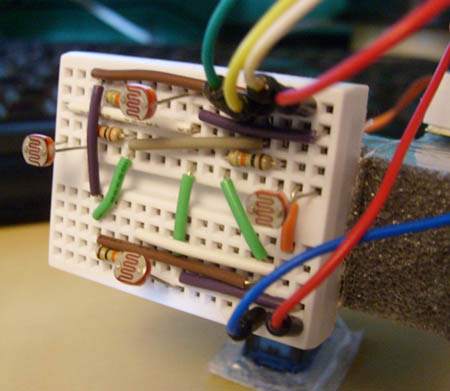
And of course some wires, and a breadboard or two :). Next step is to wire it all up, I’ve made a drawing in Fritzing that you can follow. Basically each photoresistor is wired likes this:
void loop()
{
// Reads the values from the photoresistors to the Left and Right variables.
Left = analogRead(inputPhotoLeft);
Right = analogRead(inputPhotoRight);
// Checks if right is greater than left, if so move to right.
if (Left > (Right +20))
// +20 is the deadzone, so it wont jiggle back and forth.
{
if (pos < 179)
pos++;
myservo.write(pos);
}
// Checks if left is greater than right, if so move to left.
if (Right > (Left +20))
// +20 is the deadzone, so it wont jiggle back and forth.
{
if (pos > 1)
pos -= 1;
myservo.write(pos);
}
// Added some delay, increase or decrease if you want less or more speed.
delay(10);
}
PS. If you got any questions etc, please take it in my forums post here.
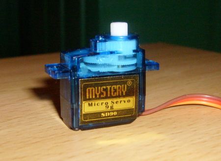
It’s always good to have servos that works like a geared motor. That also can go in both direction and speed is adjustable, it’s very handy in robotic project or general vehicles. The servo I’m using is a Mystery Micro Servo 9g SD90. But most of these small servos got the same internals so I guess you can use this on other servos.
1. Remove the stickers on both sides, and unscrew the four long screws that goes from the bottom to the top. One in each corner of the servo.
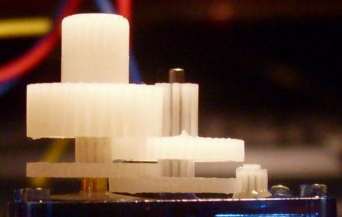
2. Gently lift off the top cover to uncover all the gears. Notice, it’s smart to remember the correct order of the gears, so that when you put them back you know what goes where. But I took a picture close to make it easier to remember where they all go. Use picture below for this purpose.
3. Remove all gears, no need to clean the grease off. Just put them in a box just for now.
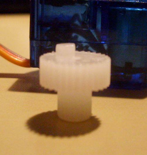
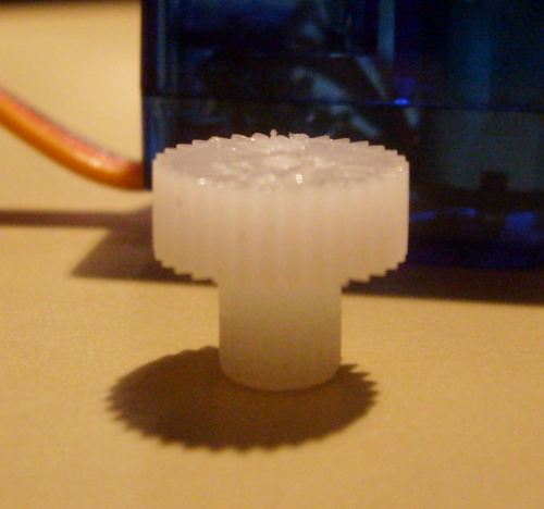
4. Take the top gear and snip the little plastic bit off it, look at pictures below. This is the part that stop the servo from going more than 180 degrees.
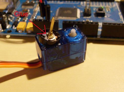
5. Now we need to glue the potmeter, look at picture below. Just remove the plastic cap thats on the shaft of the potmeter to show it’s internals.
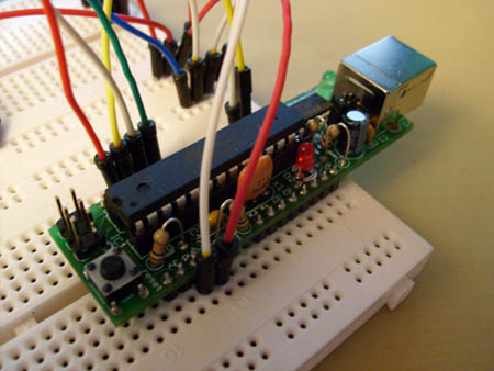
6. Attach the servo to the ardunio, using pin 9 as the signal. Use this program or just some other program that gives the servo 90 degrees. If the potmeter is centered the servo should stop the motor from turning, if it doesn’t try to turn the potmeter shaft one or the other way until it stops. You now got it centered so that 90 is stop, just add some glue to the internals of the potmeter to keep it locked. Before moving onto step 7 let the glue dry.
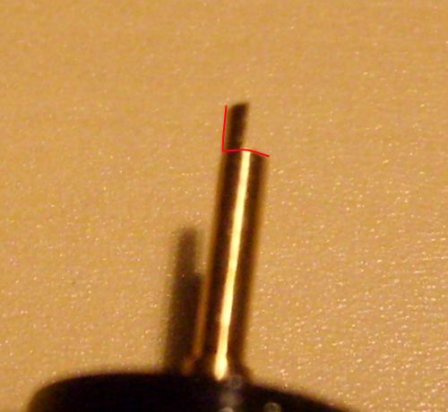
7. You now need to cut off the end of the potmeter shaft, this keeps the potmeter shaft from moving. Look at picture below for more info.
8. Now you only need to put it all back together. Just use the picture in step 2 for reference when adding all the gears.
There you are, now it should work like a continous servo. Any questions just leave a comment below.