Guide: Flashing Hobbywing Skywalker 20A ESC with BLHeli Firmware

Category : Arduino, Electronics, RC

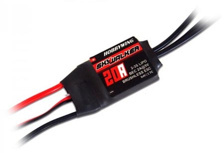
This guide will tell you step by step how to flash a Hobbywing 20A esc with BLHeli firmware for multirotors. It will be the same procedure for any other ESC with a silabs chip, you just need to find the pin-outs for it. Well lets get started.

You will need the following:

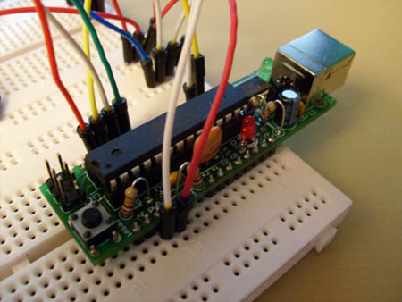
Arduino (UNO, Nano etc. I use a Mega 1280 in this guide)
Three wires (I used some male to female jumper wires)
Soldering-iron with a tiny tip
OlliW`s flash-toolkit

Step 1:

Attach your selected Arduino board to your computers USB and run the following file from the OlliW toolkit “AvrBurnTool_vxxx.exe”. Choose the type of Arduino board and select it’s COMport, then click the button “Burn All”. This will burn the flashing-tool onto your Arduino board, you can use your Arduino board for other sketches later, this will not make your board useless for other tasks.

A CMD window will popup and let you know the flashing is in progress and then done. Just close the AvrBurn tool and the CMD window. Lets move onto next step!

Step 2.

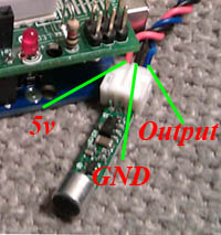
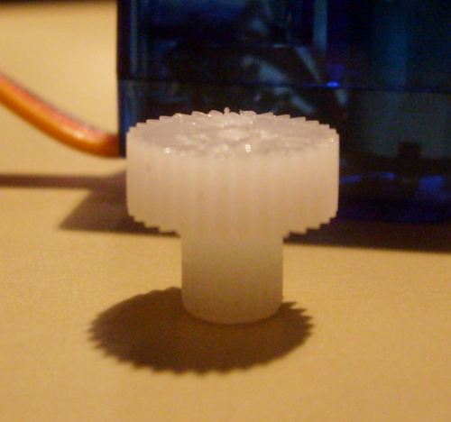
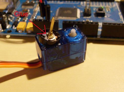
Remove the plastic wrapping around your ESC, and get familiar with the soldering points as show in the next picture (click on the picture to see a larger one).


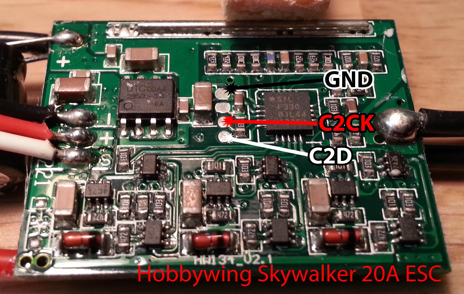
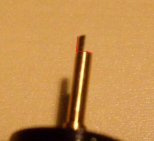
Now solder on the three jumper wires onto the pads shown in the picture above. The GND can be very tricky to solder, but after some try and fail I noticed it doesn’t need to be soldered exactly where the picture shows, but you can use the GND(black) at the servo-cable connection. Or generally any other GND. The red and white are easier, just put some tin on them first, then while you heat the wire, attach it!

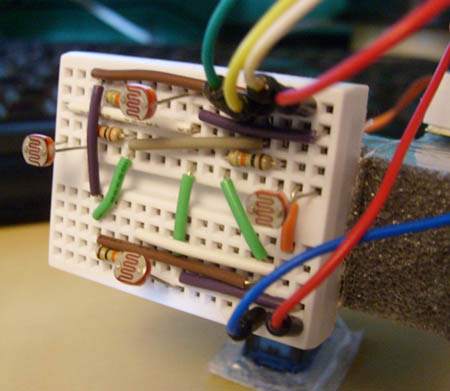
It should look something like the picture below.


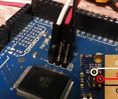
Then we attach the three wires onto the Arduino boards ISCP header, as shown in the picture below.

Step 3.

We are now almost ready to flash the ESC, but before we do so the ESC needs a lipo battery connected. Needs to be powered on while flashing. The start the file  “BLHeliTool_v100.exe” and choose your ESC make, model, type. As shown in the picture below.


Or choose the firmware file directly “BLHeliHexFiles\SKYWALKER_20A_MULTI_REV9_3.HEX “, and hit Flash!

If everything went smooth it should say “Flash hex file… DONE!” 🙂 To verify this click the “Setup Basic” tab and select READ, this will tell you the firmware type.

HAPPY FLASHING!

PS! At the moment 9_3 firmware will cause “twitches” when used on the Skywalkers, a new fix is in the works. And will be released in a matter of days.

UPDATE: v10 firmware is now available, check out this link.


Tutorial: C# Communicating with Arduino over Serial

11

Category : Arduino, Electronics, Windows

In this tutorial I’ll try to show you how to easily tell an arduino what to do from a C# program using serial communication. The only thing the C# program does is send a byte to the arduino, and the arduino program will then set pin 13 to HIGH or LOW.

Lets start with the C# sourcecode, it’s written in C# Express 2010 which you can download for free here. Get the C# project files:

Download CSharpEasySerialSource.zip

I tried to comment the code so that it should explain most of the stuff going on. But it’s pretty basic, you select the current comport then hit Connect. If you selected the correct port that the arduino is using it should now be connected. The textbox only takes numbers, writing text there will only result in it being converted to bytes.

When you click Send it will try to send the contents of the textbox to the arduino. In my example code I used “0” and “1” for turning off an on the LED. Lets look at the Ardunio example:

What the program does it’s listening on the serial port. And when it receives a “1” pin 13 goes HIGH, and if it receives “0” it goes LOW. Pin 13 is in most cases a LED thats on the arduino board, so you only need a bare arduino to test it. And if you don’t know any C# and just want to use the program to control a arduino I’ve created a zip file containing only the .exe file for the program:

Download CSharpEasySerial.zip

Arduino, LEDs that blinks to the Music!

3

Category : Arduino, Electronics

I always wanted to make something out of the microphone sensor I got, it’s just been laying in a compartment-box until recently when I got the idea of a music beat blinker.

Basically it just reads the analog value from the mic and converts it to a 0-1023 value, but since the microphone sensor I got is meant for 12 volts, it only ranges from 0 – 5-600 on 5 volts. But it works just as good, only it’s not as sensitive as it should be. When playing music that is never a problem hehe.

The microphone sensor I use is one I found on eBay some time ago, just search for “Arduino Sound Sensor Module” they cost around 5$. And are very easy to use, only ground it and feed it with 5 volts and stick the output to a analog input on the Arduino. I’ll also post the program code for the Arduino, it’s the same thats used in the video below. If you want to make something like this yourself using my example, you only need 5 LEDs or more. And just wire them to the digital pins 2-5, and of course the mic to analog 0. Code example can be found in the bottom of this article.

Here is a video showing the LEDs blinking to the music.

Program code example:


Tutorial: Host your own Minecraft server

2

Category : Minecraft

Why not?

First off we need to download the server software, you can find it here. Look further down on the page and you’ll see a link to a Minecraft_server.exe, thats the one you need. Download it and put it in a folder, lets call it Minecraft_Server.

Now lets run the .exe file you just downloaded so that it creates the config files, and close it when it’s done generating the spawn point. Now your folder should look something like this.

world = the server map, it’s just been autogenerated.
banned-ips.txt = the list of banned IP adresses.
banned-players.exe = banned users.
ops.txt = server operators, users that can kick and ban etc.
server.log = the logfile.
server.properties = server settings, this one is important.

Before we go and configures the server properties, we need to open a port on your router or whatever your behind. Find the routers IP adress, easiest way is to enter cmd.exe and write “ipconfig”. Then look at whats the default gateway. Mine is 192.168.1.1.

So just write the ip adress in your browser(Firefox, Chrome etc) and log on to the router. In this tutorial I’m using a Dlink DIR-655, but it’s done almost the same on most of the routers out there. Click into Advanced, and find Virtual Server. Check the check-box and write the name of the port, just whatever you want to call it. Fill in your computers IP, it can be found the same way we found the routers address, just look for IPv4 Address. Set public and private port to 25565, which is the default minecraft-server port, protocol select both. It should look something like this:

Now just run the server .exe and it should be up and running! When thats done, you can check with this page that the port you opened is open. Of course there are many mods and server managers that are way better than the default one, but at least you get the idea of how you host your own server.

Any questions, or something I forgot? Post a comment!

How to make a security alarm using LDR and Laser!

1

Category : Arduino, Electronics

How about a easy and simple tutorial on how to make a sort of security sensor using laser and a light dependent resistor?

It’s just as simple as this, the LDR reacts when it gets less light than the laser-dot in the center of it. Which is when something comes in the lasers way. So then you know when something passes the invisible line between the laser and the LDR.

Lets begin with what components you need:

1x Laser Emitter/Pen
1x LDR
1x Resistor 10k (doesn’t have to be 10k ohms)
1x Piezo Buzzer (you can use a LED or anything else you want)

And of course a Arduino board of your choice, and some wires.

Lets wire it all up like this:

Things to notice, buzzer is grounded and the + wire is on the digital 10. Laser is just ground and +5v to make it light constantly. The LDR is in a voltage divider with a resistor, we take out the readings in the middle where the yellow wire is, and it’s attached to the analog 0.

A picture of the LDR.¨

When all this is wired up, just put this code and run it.

[youtube=http://www.youtube.com/watch?v=IzEDspdWjxU;ap=%2526fmt%3D18&w=425&h=344]

Thinking about starting with Arduino? Read!

4

Category : Arduino, Electronics

Hi

I just want to write a few words for those new to Arduinos, or those looking for tutorials, guides etc. If you haven’t got a Arduino board yet, you can get one from several places, I’ll list some of my favorite shops. And of course you also need the Arduino Software!

Sparkfun
Seeedstduio
Adafruit

Or, Modified Electronics for the great Pico! (not recommended for beginners, you’ll be better of with a normal board).

What you are looking for is the Arduino Duemilanove, the USB board. Which will suit most your needs. It’s very easy to use, and wires can be plugged right into it. Later on you might want a Boarduino or maybe a Pico as mentioned above, they are great for using in combination with breadboards! Alternatively you can get the Starter kit, almost all shops got these. Sparkfun got a nice kit, which is worth a look.

If you should want more I/Os, or just more space for code the Arduino Mega is a great choice! Or the Sanguino!

Parts!

You will always need parts, resistors, leds, breadboards, wires etc. I’ll list up a few shops that I use the most.

Futurlec

Lots of cheap basic parts! recommend the resistor packs, and they also got cheap breadboards. And all of the shops mentioned above stock parts too. For jumper-wires I recommend these at seeedstudio. Futurlec also got some nice jumper-kits. For extra small breadboards these at Seeedstudio are very nice!

Pololu

Great site for robotics, motors, gearboxes etc. They also got a nice tracked chassis. They got a lot great products, sensors, motor controllers, etc.

Tutorials/Guides/etc

1. The basic guide, from sparkfun. You should start with this!

2. The Complete Beginners Guide to The Arduino

3. Adafruit’s Arduino Tutorials

4. Arduino.cc`s Tutorials

5. Arduino.cc Reference! Not tutorials, but handy!

Also the Libaries page at Arduino.cc is great! I’m sure you’ll find something to use in several projects!

Well, thats all I’ll write for now. I’m sure I left out alot, and will update this post when I find something new to add 🙂

PS. If you got any questions etc, please take it in my forums post here.

Arduino: Showing CPU load with 9 leds!

6

Category : Arduino, Electronics

My new project, is a simple led-strip which shows CPU load. 9 led’s are used for this, could have used more but my tiny breadboard couldn’t hold more. Anyhow, it uses serial communication to receive how much the totalcpu usage is. For this you need a C# program running on your computer, it just sends a value from 0-100. And the Arduino reacts and lights up leds accordingly to how much load your CPU got.

I will not go into how you make the program in C#, therefore I’m uploading the .exe here for you to download. I’ll also include the source-code for it.

What you need?

1x Arduino
9x LEDs
Some wires

1. Wire it all up like in this Fritzing picture.

2. Load up the Arduino with the following program.

3. Download the C# program here.

When you start the .exe file, you only need to select which Com port the Arduino is using. And the click connect, and then it should start communicating with the Arduino. And show cpu load.

[youtube=http://www.youtube.com/watch?v=ecbdUhiOWes&w=425&h=344]

PS. If you got any questions etc, please take it in my forums post here.

Bo/arduino advanced light tracker.

10

Category : Arduino, Electronics

Made a followup to my light tracker, except this one can go up and down. So it follows light in more directions than the other ones.

[youtube=http://www.youtube.com/watch?v=0Fw6ausjl9o&w=425&h=344]

Made of some cheap plastic-foam, wont last forever but long enough for me to test it.

Program Code!

PS. If you got any questions etc, please take it in my forums post here.

How to make a light tracker using arduino & photoresistors!

22

Category : Arduino, Electronics

[youtube=http://www.youtube.com/watch?v=iEhX27ahreI&w=480&h=385]

This is how to make a simple light tracker/follower with the Arduino. The components you need apart from the Arduino is:

2x Photoresistors: “PHOTOCELL2 Miniature Photocell”.
2x 470 Ohms resistors.
1x Servo.

And of course some wires, and a breadboard or two :). Next step is to wire it all up, I’ve made a drawing in Fritzing that you can follow. Basically each photoresistor is wired likes this:

PhotoR       470Ohms
+5    o—///–.–///—o GND
|
Pin 0 & 1 o——-

Program Code:

#include <Servo.h>

Servo myservo;

int pos = 0;  // Variable to store the servo position.
int inputPhotoLeft = 1; // Easier to read, instead of just 1 or 0.
int inputPhotoRight = 0;

int Left = 0; // Store readings from the photoresistors.
int Right = 0; // Store readings from the photoresistors.

void setup()
{
myservo.attach(9); // Attach servo to pin 9.
}

void loop()
{
// Reads the values from the photoresistors to the Left and Right variables.
Left = analogRead(inputPhotoLeft);
Right = analogRead(inputPhotoRight);

// Checks if right is greater than left, if so move to right.
if (Left > (Right +20))
// +20 is the deadzone, so it wont jiggle back and forth.
{
if (pos < 179)
pos++;
myservo.write(pos);
}

// Checks if left is greater than right, if so move to left.
if (Right > (Left +20))
// +20 is the deadzone, so it wont jiggle back and forth.
{
if (pos > 1)
pos -= 1;
myservo.write(pos);
}

// Added some delay, increase or decrease if you want less or more speed.
delay(10);
}

PS. If you got any questions etc, please take it in my forums post here.

Guide: How to make a 9g micro servo continuous

8

Category : Arduino, Electronics

It’s always good to have servos that works like a geared motor. That also can go in both direction and speed is adjustable, it’s very handy in robotic project or general vehicles. The servo I’m using is a Mystery Micro Servo 9g SD90. But most of these small servos got the same internals so I guess you can use this on other servos.

1. Remove the stickers on both sides, and unscrew the four long screws that goes from the bottom to the top. One in each corner of the servo.

2. Gently lift off the top cover to uncover all the gears. Notice, it’s smart to remember the correct order of the gears, so that when you put them back you know what goes where. But I took a picture close to make it easier to remember where they all go. Use picture below for this purpose.

3. Remove all gears, no need to clean the grease off. Just put them in a box just for now.

4. Take the top gear and snip the little plastic bit off it, look at pictures below. This is the part that stop the servo from going more than 180 degrees.

5. Now we need to glue the potmeter, look at picture below. Just remove the plastic cap thats on the shaft of the potmeter to show it’s internals.

6. Attach the servo to the ardunio, using pin 9 as the signal. Use this program or just some other program that gives the servo 90 degrees. If the potmeter is centered the servo should stop the motor from turning, if it doesn’t try to turn the potmeter shaft one or the other way until it stops. You now got it centered so that 90 is stop, just add some glue to the internals of the potmeter to keep it locked. Before moving onto step 7 let the glue dry.

7. You now need to cut off the end of the potmeter shaft, this keeps the potmeter shaft from moving. Look at picture below for more info.

8. Now you only need to put it all back together. Just use the picture in step 2 for reference when adding all the gears.

There you are, now it should work like a continous servo. Any questions just leave a comment below.

Video of the final product: